
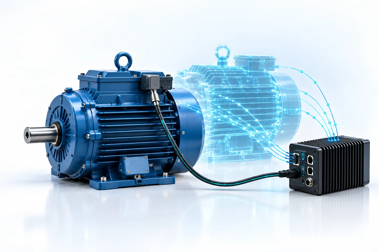
Give the motor a measurement history
For a motor manufacturer, condition monitoring can extend the relationship beyond delivery. A customer can receive a motor with a suitable sensor mounting arrangement and a defined commissioning process. The service team can then review measurements alongside operating conditions and inspection findings. Start with one motor series and one maintenance question, rather than a promise to predict every failure.
A pilot may evaluate factory installation or a sensor-and-mounting kit supplied with the motor. Training, periodic data review and maintenance reports can be scoped separately. The package, responsibilities and service frequency should follow the pilot results.
What ForgePulse contributes
ForgePulse provides three-axis acceleration measurements for vibration monitoring, local temperature measurements and three-axis magnetic-field measurements, with timestamped local recording. These signals supply evidence about changing behaviour; their interpretation depends on the installation and the operating state.
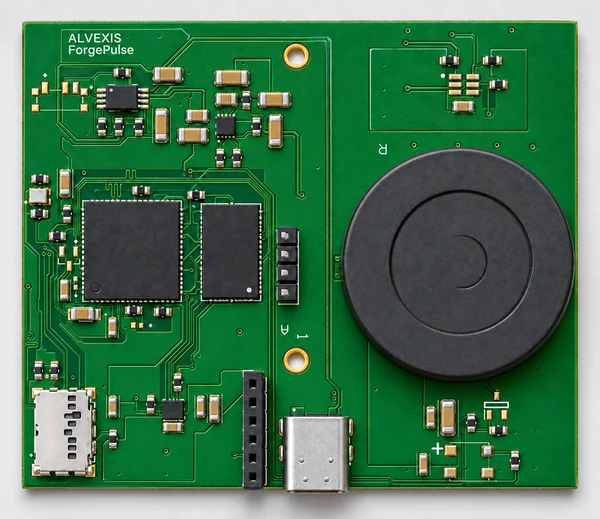
- Vibration: define the mounting position, orientation, measurement bandwidth and acquisition windows for the motor and the condition being investigated.
- Local temperature: the reading describes conditions near the sensor. Relating it to the motor surface requires an understood thermal path and verification; it does not directly measure winding temperature.
- Magnetic field: use measurements as an additional signal where the application supports it. Mounting position, nearby equipment and operating conditions affect interpretation.
Local recording supports review where a continuous connection is unavailable. Any connection to an edge computer, plant network or remote service must be specified for the chosen configuration. The device name or a conceptual diagram does not establish a particular radio protocol or a live cloud connection.
From installation to a useful maintenance decision
- Mount consistently. Select a rigid location near the relevant bearing housing and verify the mechanical attachment.
- Record a baseline. Capture measurements under known speed, load and process conditions. Record the motor identity and sensor position.
- Measure and retain context. Set acquisition windows, timestamps, storage and power settings around the maintenance task.
- Review changes. Compare similar operating states and agree how device indications or analysis results should trigger an inspection.
- Close the loop. Attach technician findings and service events to the measurement history so the next review has better evidence.
When condition monitoring supports predictive maintenance
Condition monitoring tracks measurements and their changes. A predictive-maintenance application also needs a defined fault or maintenance objective, relevant history and validation against events that were not used to develop the analysis. An unusual vibration pattern is a reason to investigate; it is not automatically a fault diagnosis or a remaining-life estimate.
Agree practical pilot criteria: repeatable measurements, adequate coverage of operating states, useful warning behaviour and a manageable review workload. State which local evaluation and alert functions are included in the delivered firmware and test them on the intended equipment.
Add thermal imaging where it answers another question
A separately integrated thermal camera can observe accessible surface-temperature patterns across the motor, bearing housing or associated equipment. It can complement vibration data when measurements are taken under comparable conditions. ForgePulse’s local temperature measurement is not thermal imaging, and an infrared camera does not reveal every internal fault.
Define camera placement, visible surfaces, measurement settings and timestamps before combining the data. Sensor selection, edge processing, mechanical integration and the interpretation workflow belong in the custom project scope.
Build the data foundation for a motor digital twin
A digital twin connects an identified physical motor to a maintained digital representation. Useful inputs can include measurement history, operating state, motor parameters and maintenance events. A three-dimensional rendering can help navigation, but the value comes from how the model is connected to evidence and used to answer an operational question.
Start with a trustworthy record of the asset and its measurements. Add the required data connection and model, define how often it is updated, and validate any scenario or prediction it produces. ForgePulse can contribute sensing data; ForgeEdge can be evaluated for local processing when the interfaces and workload fit. A complete digital-twin service is a separate integration and modelling scope.
Adapt the package to a motor series
Mounting geometry, enclosure, battery access, recording access and the measurement duty cycle should be designed together. Alvexis can scope the electronics, embedded software, mechanical adaptation and data interfaces around the manufacturer’s requirements. Product identification and documentation can also be discussed as part of the OEM arrangement.
Start with a joint pilot
Share the target motor series, speed and load range, installation constraints, maintenance problem and available service history. Choose representative pilot units and agree who installs, reviews and acts on the data. Evaluate the technical result and customer usefulness before expanding the package to more motors.
Predictive maintenance vs preventive maintenance
Preventive maintenance follows a planned interval or usage rule. Predictive maintenance uses evidence of condition to support a maintenance decision. A vibration sensor, current transducer and temperature measurement observe different parts of motor behavior. Compare measurements at similar load and speed before treating a change as a fault indicator.
Digital twin technology needs a measurement history
A digital twin model connects the physical motor to a representation that can be updated with operating data. Record sensor position, sampling settings, load and maintenance events alongside the signal. Useful digital twin examples begin with a specific decision, such as comparing two operating states or checking whether a repair changed a recurring vibration pattern. Predictive maintenance in manufacturing also needs a process for reviewing alerts and recording the outcome.